![]()
A collection space for my personal and professional works, as a portfolio, a curriculum vitae and as a personal record for myself.
![]()
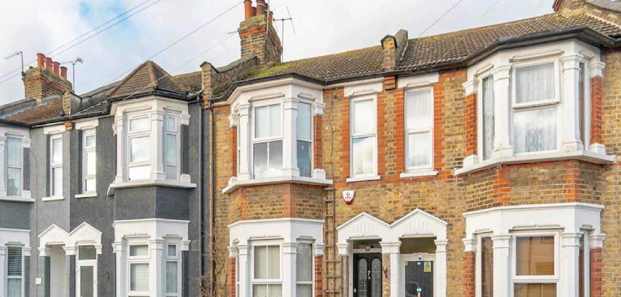
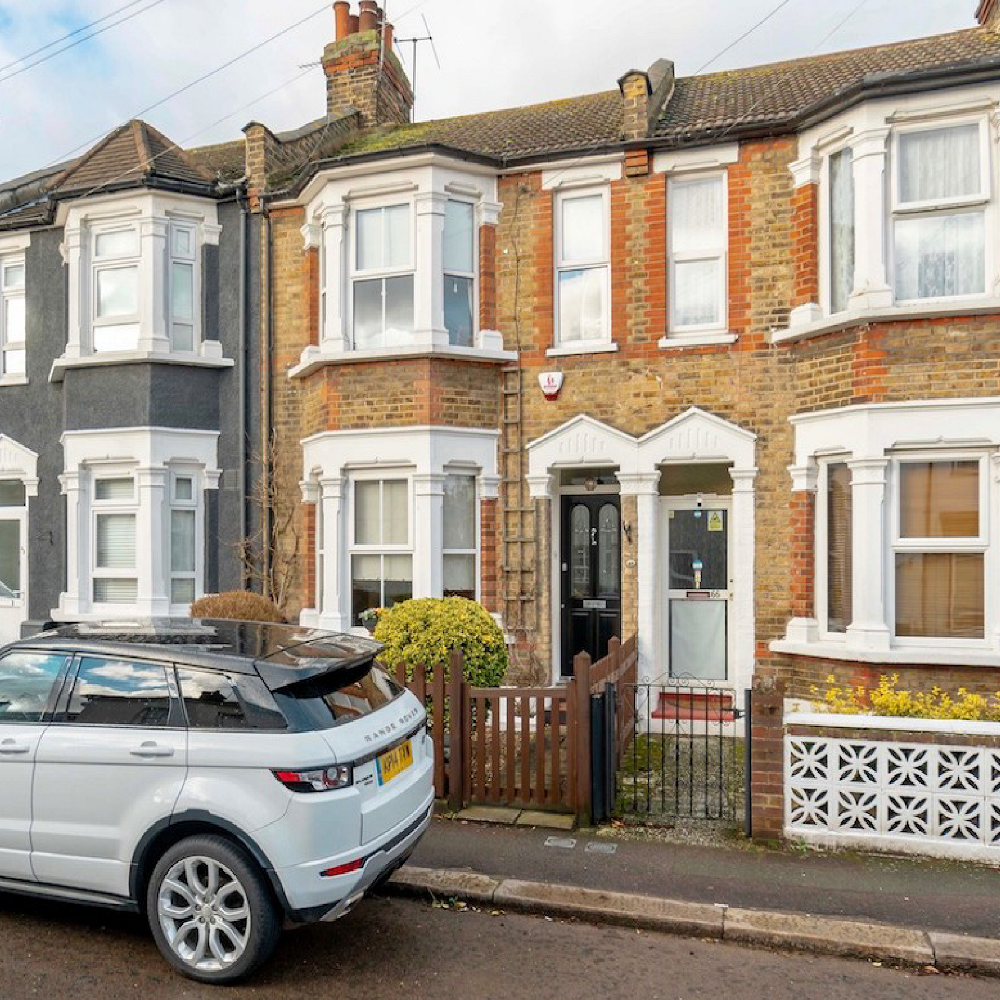
I was approached by a young couple to design a new loft conversion for their terrace property in Woodford Green, Essex.
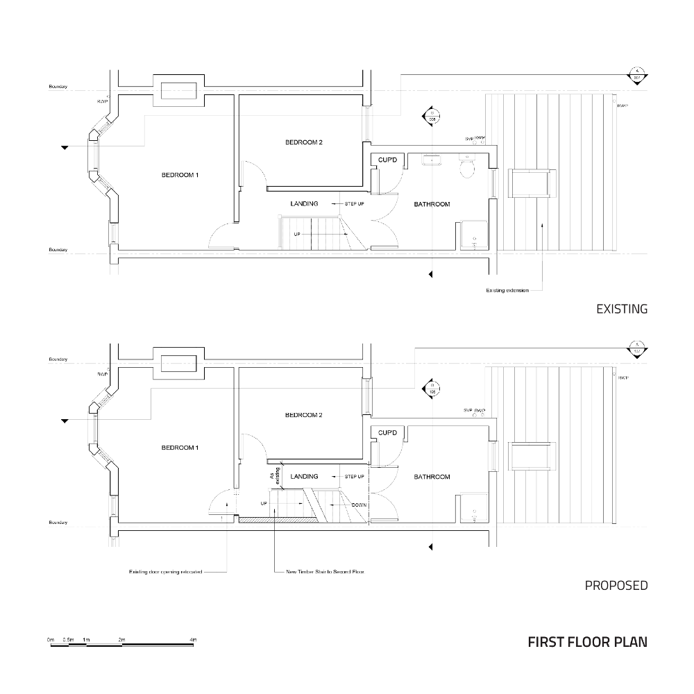
The clients, seeking to expand the available living space of the property looked to convert and expand the existing loft storage space to create an additional 2 bedrooms and a bathroom, to add to the existing 2 bedroom, 1 bathroom at First Floor.
Working under lockdown conditions outside the UK, I suggested that if they were willing to carry out the measurement survey of the property, time could be saved in the preliminary stages, and a more competitive rate could be agreed for the drawing services. Instructions were sent to the client, and, keen to get the ball rolling on the project, they had completed the survey within a week of the original email. Working to the survey with the aid of photos, an accurate set of existing drawings could be produced, and, without any fuss, the project was underway…

After a brief conversation, it was ascertained that the project could be realised within the scope of Permitted Development.
Permitted Development Rights are a set of rules which define to what extent a householder is permitted to increase the size of their home, without the need to go through the extensive Planning Permission process. Permitted Development was introduced by the national government to simplify the planning process, and speed up the approval process for simple, tried-and-tested household improvement projects. The benefits of which are considerable time- and cost-saving for both authorities and for clients.
Following a change in Permitted Development rules in recent years, the couple were able to convert and expand their loft space up to a maximum 40 cubic metres, to accompany the existing rear kitchen extension of nearly 40 cubic metres which had been realised by the former occupants. Upon the completion of the new loft conversion, this would mean an expanded living space of nearly 80 cubic metres from the original 200m3 of the original property.
To certify that the proposed work would fall within Permitted Development Rights, the client was advised to submit an application for Lawful Development prior to commencement of the works. A short application form was filled in online and the preliminary drawings were uploaded to the Planning Portal via. Redbridge Council website. After just 5 days, consent had been granted and a certificate was issued to the client to approve the works.

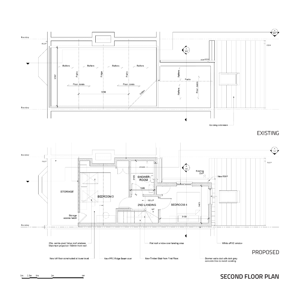
Permitted Development Proposed Loft Drawing
To satisfy all relevant Building Regulations, a more detailed set of drawings, including annotated plans, elevations, sections and details, was produced to more accurately describe the design to the Building Control inspector and the Building Contractor.
In addition, a set of Detailed Notes was produced to describe how the proposed design responded to minimal requirements of Fire Safety, Energy Performance, and Accessibility set out in the respective Approved Documents B, K, L1B & M. Designed to accompany the drawings, the Detailed Notes provided a means to neatly cover all aspects of the design, such as lighting, electrical works, ventilation, window glazing, fire alarms and drainage which would otherwise clutter the drawings. In addition, the structural and material build-up of proposed and retrofitted walls, floor and roof could be described in detail. The result is a concise document which could be easily assessed and verified by Building Control, and which served as a point of reference to the building contractor.

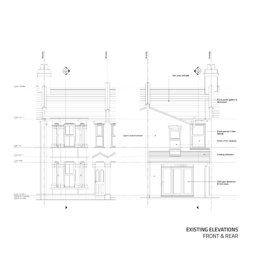
Building Regulations Drawings
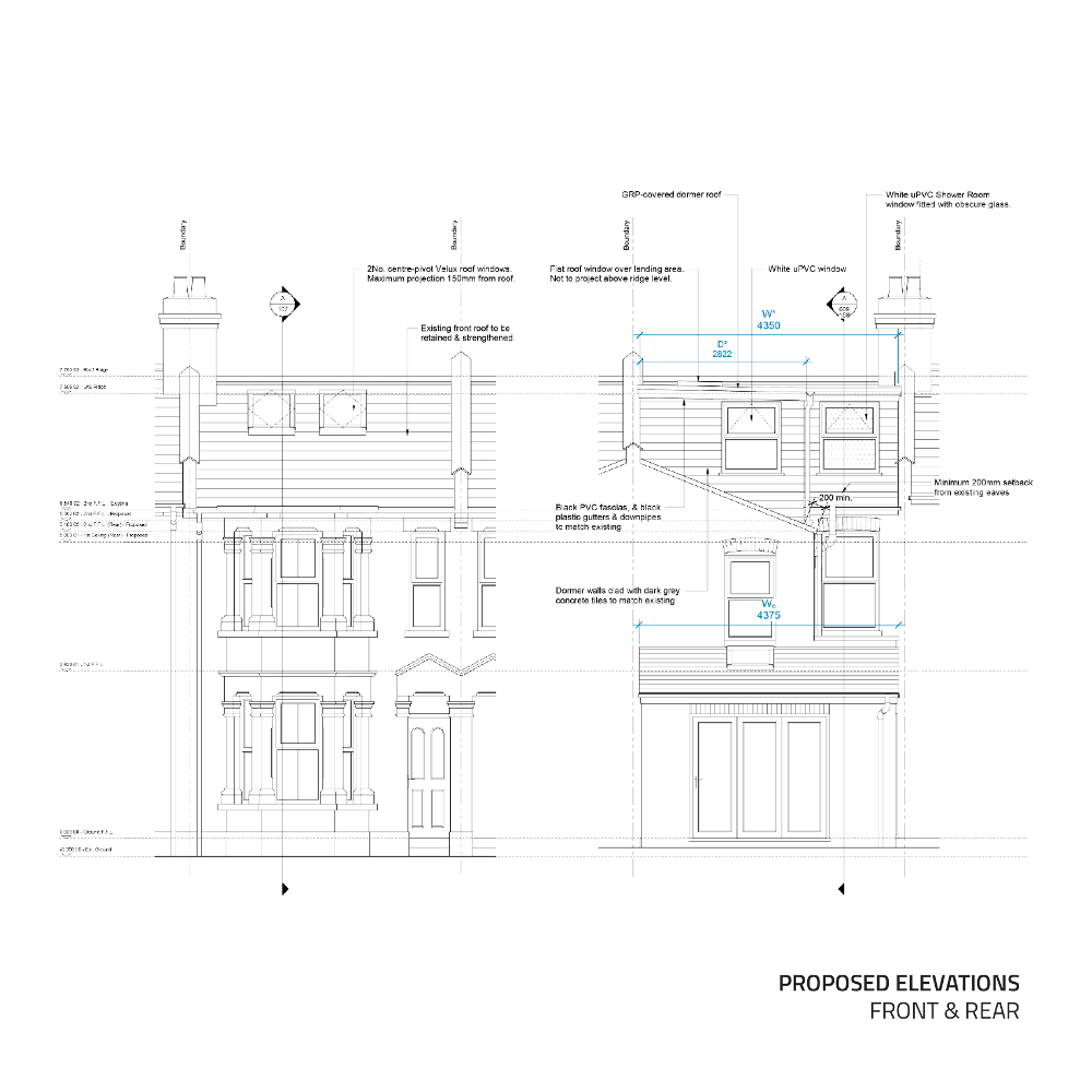
Since Permitted Development restricts roof alterations only in certain ways, there is a usual ‘look’ to loft conversion for each house type. For a Victorian Terrace of this type, a conversion usually involves a dormer to ‘box-out’ the rear roof, since nothing more adventurous than a Velux roof window is allowed to be seen from the front of the property under planning laws. The flat roof dormer allows for a comfortable habitable area beneath a flat ceiling without the need to crouch at any part of the roof.
The space beneath the front roof is maximised with a vaulted ceiling, and terminates in a short ‘dwarf’ wall to the front, beyond which the low ceiling renders the space usable only as loft storage.

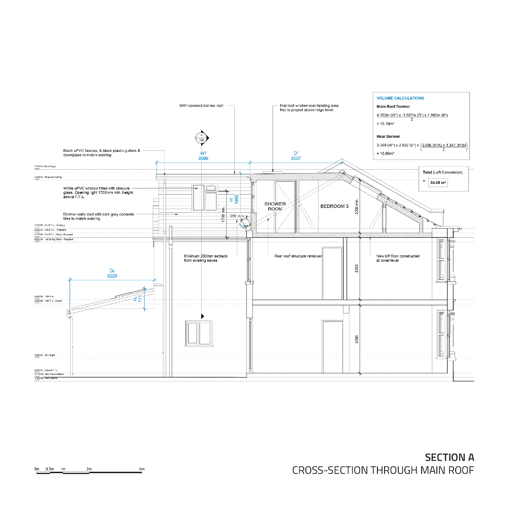
Permitted Development Section through Proposed Rear Dormer
In this particular project, height was of the essence. The headroom at the apex of the existing loft was around 1.93m. Since planning law restricts the lifting of the existing roof ridge, and Building Regulations specifies a certain depth to the new roof insulation in the converted roof space, the available headroom left over would end up far short of comfortable.
The floor therefore needed to be constructed at a lower to allow a recommended minimum 2m standing height throughout the new loft. The extent to which the floor could be dropped was determined by the head level of the existing bedroom windows. As such, the level of new ceiling was designed to coincide with the top of the bedroom windows below, creating a seamless ceiling, of height 2.35m, which continued through the bay windows, and a 2.05m minimum height in the new loft.
Due to the step down in the First Floor landing, the rear of the property enjoys greater headroom at First Floor level. To mirror this, a step was incorporated in the new floor to allow an increased headroom of 2.23m in the new rear loft bedroom above.
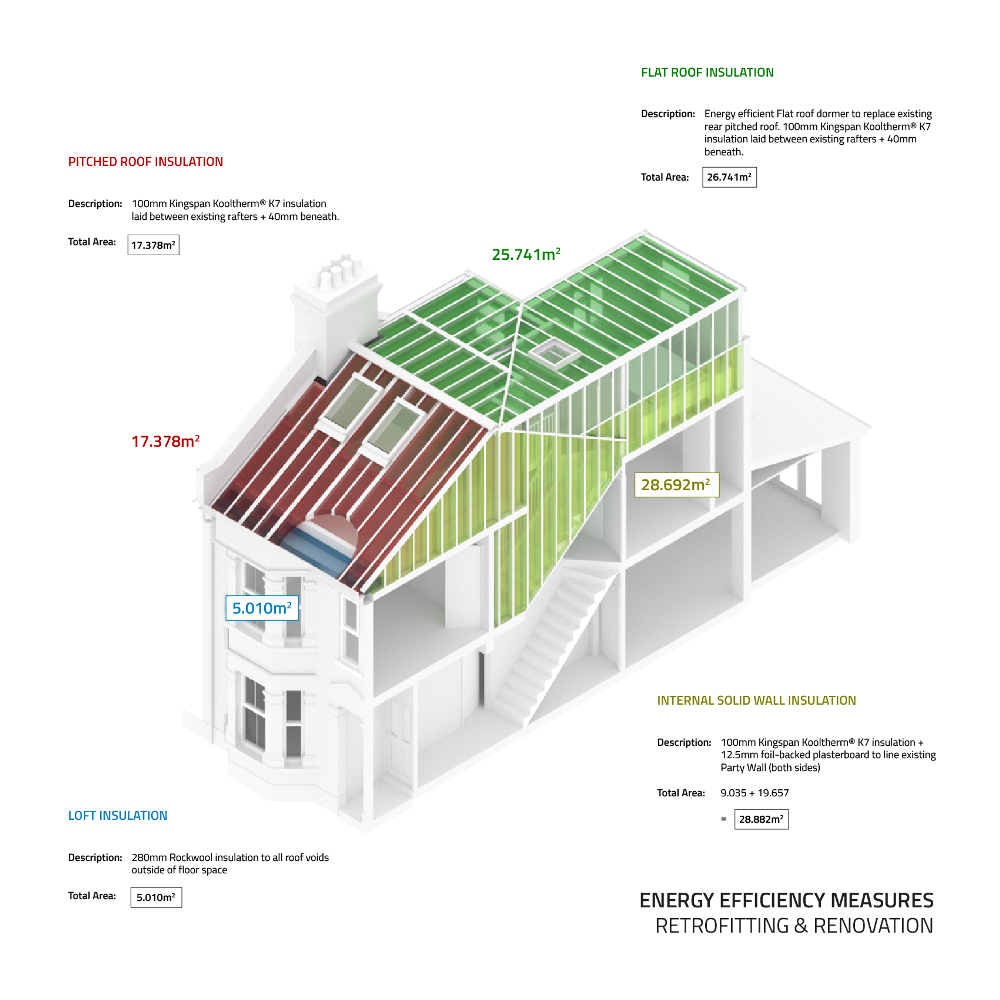
New floor joists suspended from restraint-type joist hangers fixed to timber pole plates provide the structure of the new floor. All floor voids between the joists were filled with 100mm Rockwool insulation with a 22mm tongue and groove board finish to the top, and a 12.5mm plasterboard & skim ceiling finish beneath.

Section through Proposed Loft Conversion showing new Lower Ceiling Level
The reinforcement of existing roof and construction of a new floor and dormer roof structure called for a new system of support to sustain the new loading, as the existing structure was deemed inadequate.
At the front of the new loft and concealed within the loft storage space, a new steel I-beam spans the full width of the property to carry the loading of the reinforced front roof and new loft floor safely to the solid brick Party Walls either side, avoiding the existing chimney breast on the south Party Wall side.

Proposed Floor Construction Layout
Two smaller Parallel Flange Channels (PFCs) were utilised to support the two new dormer walls at the rear of the property. Located inside the external brick wall at the level of the new floor, these beams are responsible for the loading of the dormer wall and the new floor. At the opposite end of the new floor joists, timber pole plates connect the new floor joists via joists hangers to the existing brick walls of the building.
At roof level, timber carcassing of 150mm x 50mm joists provides the structure of the flat roof dormers. At the connection of the main dormer to the roof ridge, an additional parallel flange channel reinforces the existing timber ridge beam to carry the loading of the new dormer. Structural timber stud walls of the dormer walls and cheeks transfer the weight of the dormer roofs to the smaller PFC channels beneath, which in turn transfer the weight to the brickwork of the existing house.

Proposed Roof Structure Layout
The proposed floor area was maximised within the limits set by Permitted Development and Building Regulations. Planning law places a tight restriction on the proximity of the new dormer walls to the existing roof eaves below. A length of 200mm of existing roof fabric had to remain intact, meaning that the ends of the roof rafters had to be retained and securely supported to the new construction, along with the existing tiles, fascias and gutters. To achieve this 200mm dimension, the new dormer walls had to sit back inside the line of the existing brick walls below, consuming the available floor space within.
On the party walls either side, we were also forbidden from building on the parapet, so the new wall structure was constructed inside existing brick separation wall. The external tile finish and fascias of the dormer cheek could stand front of this internal face, but could by no means protrude further than the centreline of the Party Wall, as the defined property boundary.
Once these criteria had been met, the remaining space is the available floor space which could be fully utilised in the new loft.

Proposed Loft Floor Plan
The larger of the two bedrooms (Bedroom 3) occupies the space beneath the existing front roof and extends backwards to beyond the line of the main roof ridge of the property.
Ample daylight is provided to the space by means of two Velux roof windows on the front roof. Such windows are allowed under Permitted Development provided that they did not protrude further than 150mm from the existing roof surface.
An eaves storage cupboard space was incorporated in the front section of the room beneath the existing roof. The existing purlin was supported with the addition of a structural dwarf wall, which transfers the load of the reinforced front and Velux windows to a new steel beam beneath, responsible for supporting the new floor.
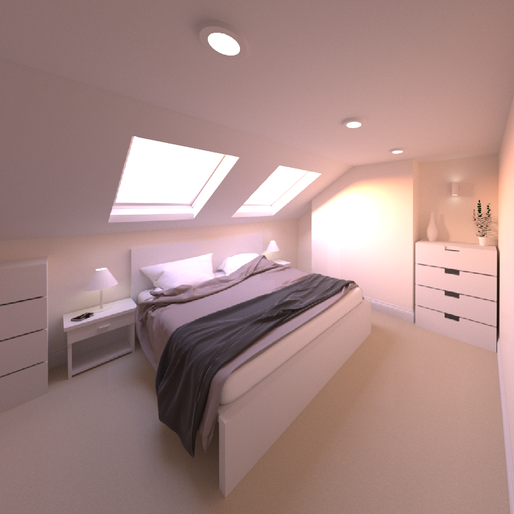
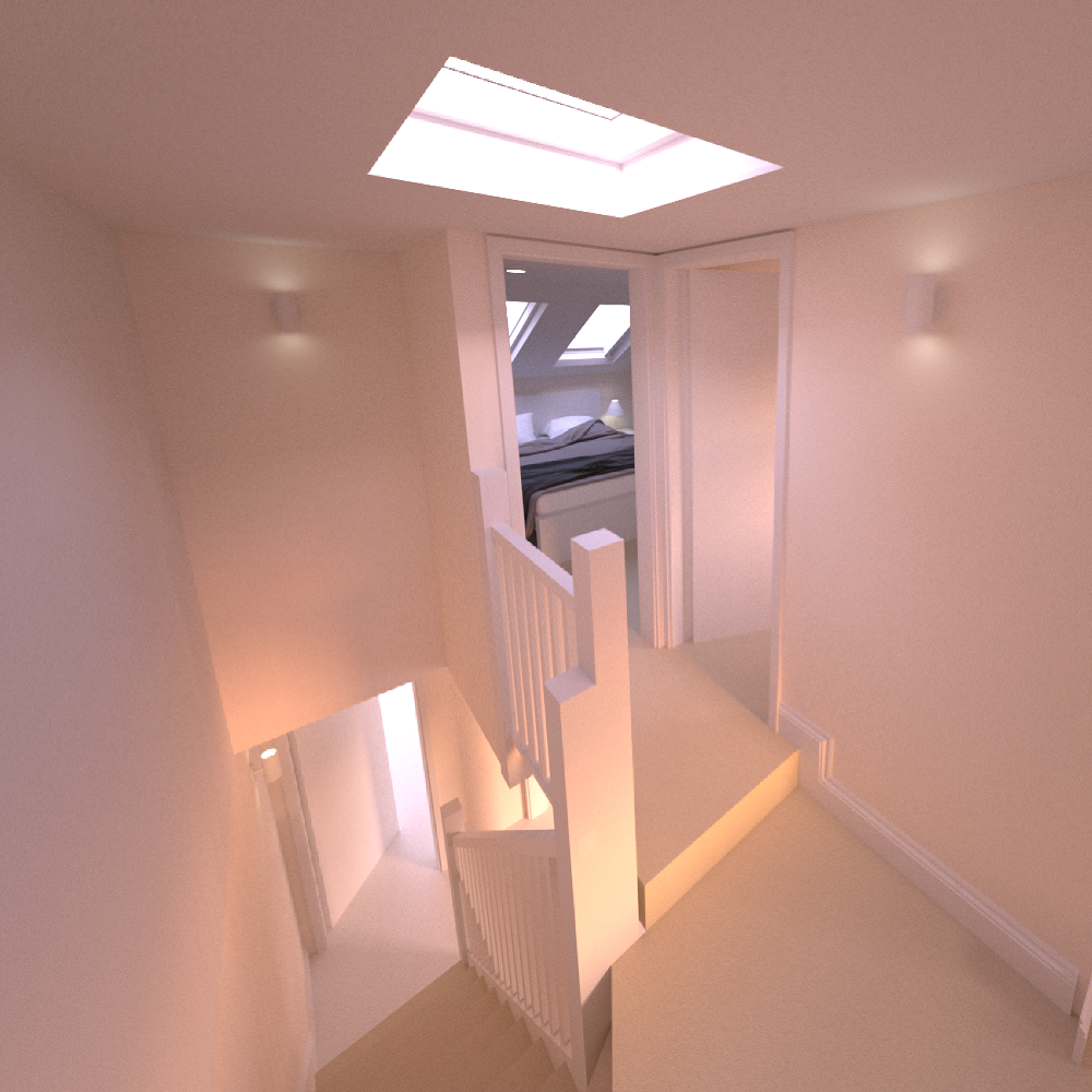
Concept Image of Proposed Loft Bedroom
The new Shower Room was located to the rear of the new loft as it needed to connect up to the existing waste. Ideally, It would have been preferable to locate it to the front, under the semi-usable pitched roof space, but the option to carry waste from front to rear was complicated and required too greater intervention to the existing structure.
The width of the proposed Shower Room was determined by the client, as any increase in width of would be to the detriment of Bedroom 3. The length was determined as the available width of the new loft minus the landing area and stairwell.
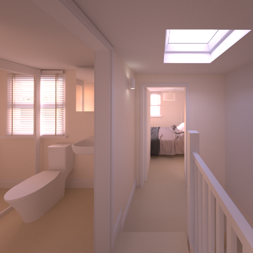
3D Visual of Shower Room & Landing
The windows to the new dormer wall had to match, to a certain extent, the windows of the existing property in size and style, but there was still scope to adjust to the preference of the client.
For any side-facing windows, such as in Bedroom 4, Permitted Development stipulates that any openings must be above the 1700 from the floor finish, and all glazing must be of obscure glass for reasons of privacy of the neighbouring properties.
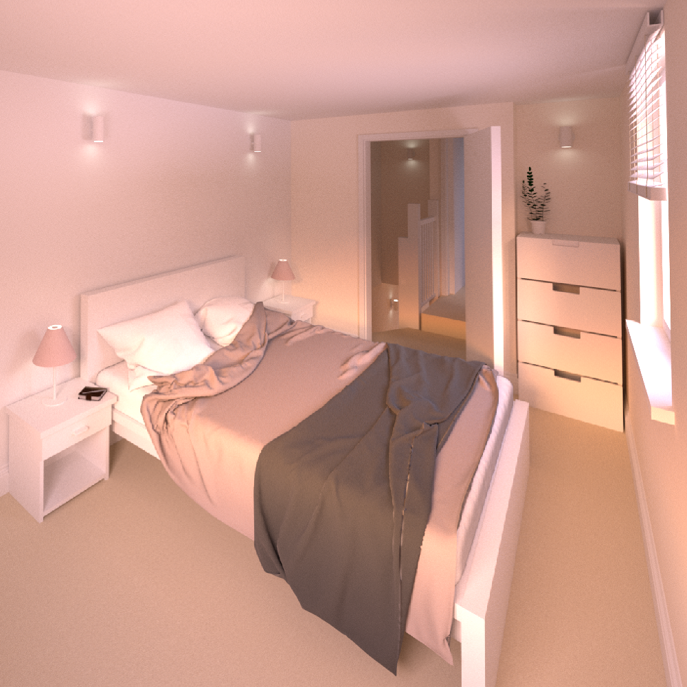
3D Visual of Rear Loft Bedroom
Follow and get updates on this, and other similar projects on social media

Follow the links below to explore other similar, related projects